
 EN
EN
 ar
ar bg
bg hr
hr cs
cs da
da nl
nl fi
fi fr
fr de
de el
el hi
hi it
it ko
ko no
no pl
pl pt
pt ro
ro ru
ru es
es sv
sv tl
tl iw
iw id
id lv
lv lt
lt sr
sr sk
sk sl
sl uk
uk vi
vi et
et hu
hu th
th tr
tr fa
fa ms
ms hy
hy ka
ka ur
ur bn
bn mn
mn ta
ta kk
kk uz
uz ku
ku
load cell wiring diagram
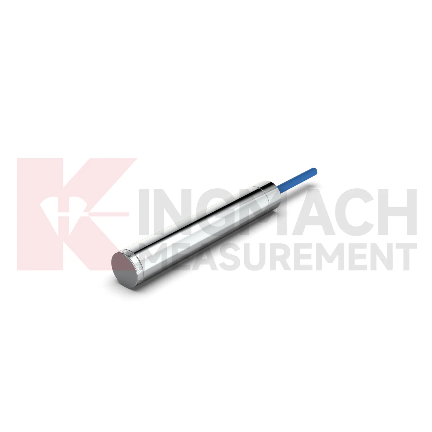
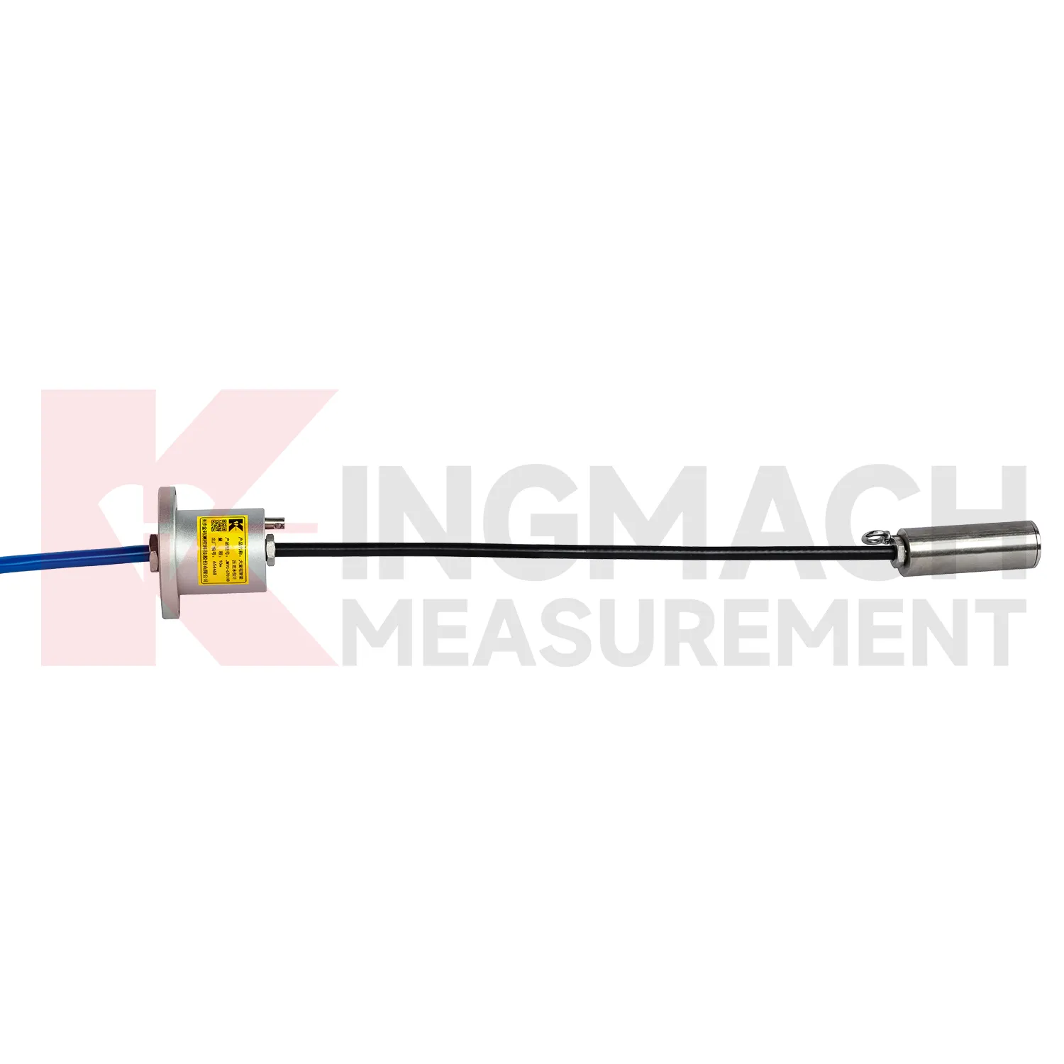
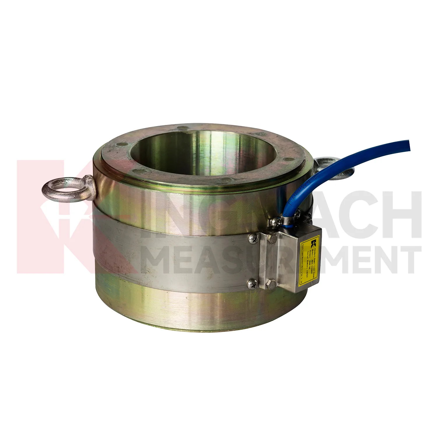
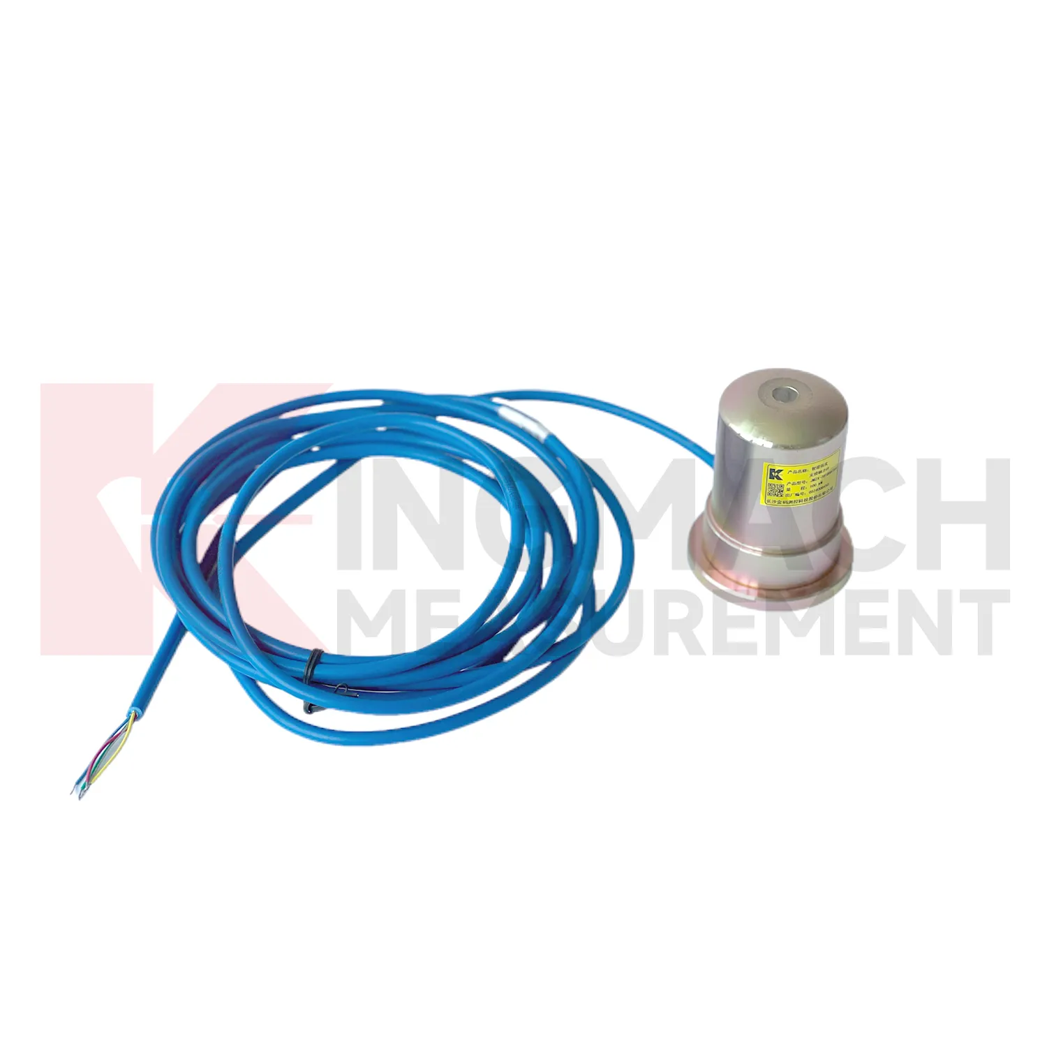
Kingmach load cell wiring diagram products give engineers several ways to measure load depending on the contact condition. Hollow load cells fit cable and anchor force work, solid load cells fit compression and bearing capacity checks, axial force meters fit steel support monitoring, and earth pressure cells fit soil or contact pressure measurement. The listed technical span is broad: 500 kN to 8000 kN for hollow models, 1000 kN to 10000 kN for solid models, 200 kN to 3000 kN for axial force meters, and 0.3 MPa to 8 MPa for earth pressure cells. Accuracy and resolution are also stated in the product files, including 0.5%FS precision on main force models and 0.001 MPa resolution for pressure cells. Kingmach adds practical field features such as waterproofing, temperature correction, memory storage, digital output, and compatible readout instruments. A good specification compares these numbers with the design load, possible overload, installation surface, service environment, and planned inspection interval. This brand context fits projects that combine several monitoring categories rather than one isolated load point. A bridge or foundation pit may require force, settlement, displacement, water pressure, and software records in the same maintenance file, so compatibility should be reviewed early. The data record should also state whether the pressure or force point will be checked manually, automatically, or by both methods during handover.
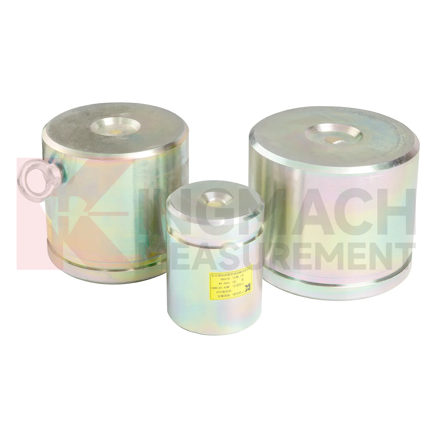
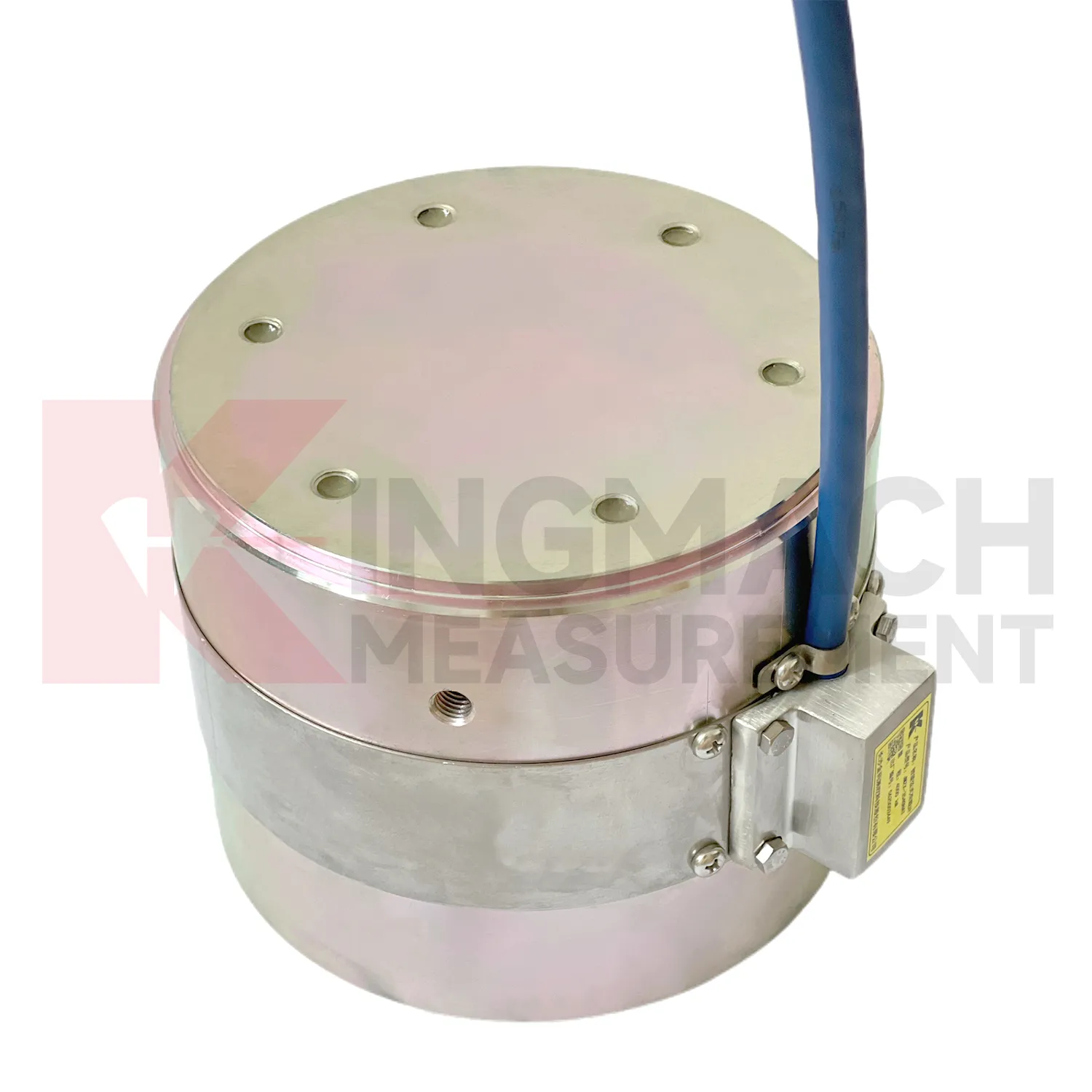
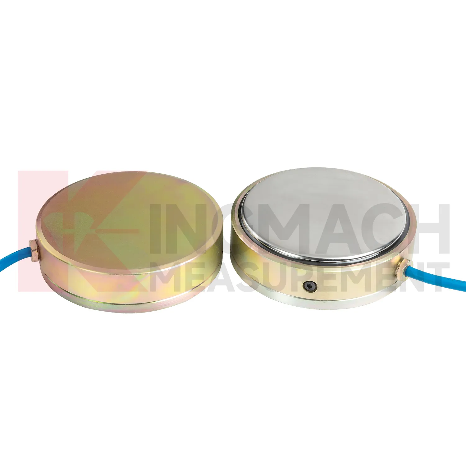
Application of load cell wiring diagram
In slope, embankment, and retaining wall projects, load cell wiring diagram helps monitor anchor force, slide resistant pile load, earth pressure, and stress change after rainfall or groundwater variation. The practical pain point is that visible slope movement may arrive late, while load and pressure trends may start earlier. Earth pressure cells in the Kingmach range are listed from 0.3 MPa to 8 MPa, with 0.001 MPa resolution, 0.5%FS pressure accuracy, and ±0.5°C temperature accuracy. Hollow load cells for anchor force cover 500 kN to 8000 kN and include temperature correction and waterproof construction. These parameters support long term points in buried, wet, or exposed conditions. Force data should be reviewed with inclinometer, settlement, water level, rainfall, and crack observation records. If anchor force drops while displacement increases, the project team has a different problem than a temporary pressure rise after rain. The instrumentation plan should therefore connect each load point to the ground behavior it is meant to explain. On slopes, cable routes should be protected against rockfall, drainage works, vegetation clearing, and surface runoff. Those mundane details matter because a broken cable can look like a dramatic geotechnical event if the hardware is not inspected first.
The future of load cell wiring diagram
Future load cell wiring diagram use will depend on cleaner data pipelines, not only stronger metal parts. Kingmach's smart load cell features, including digital output, long distance transmission, anti-interference performance, temperature correction, and stored parameters, already point toward connected monitoring. In the next few years, more projects are likely to use edge acquisition units that check whether a reading is plausible before it reaches the platform. A sudden force jump can be compared with temperature, cable condition, nearby displacement, and recent construction events. AI based warning tools may help sort routine fluctuation from patterns that deserve inspection, but they will only work when the instrument record is consistent. That places more value on channel naming, calibration certificates, zero checks, installation photos, and maintenance logs. The product direction is therefore practical: robust sensing at the point of load, reliable transmission from difficult sites, and software that helps engineers review trends without losing the original measurement context.
Care & Maintenance of load cell wiring diagram
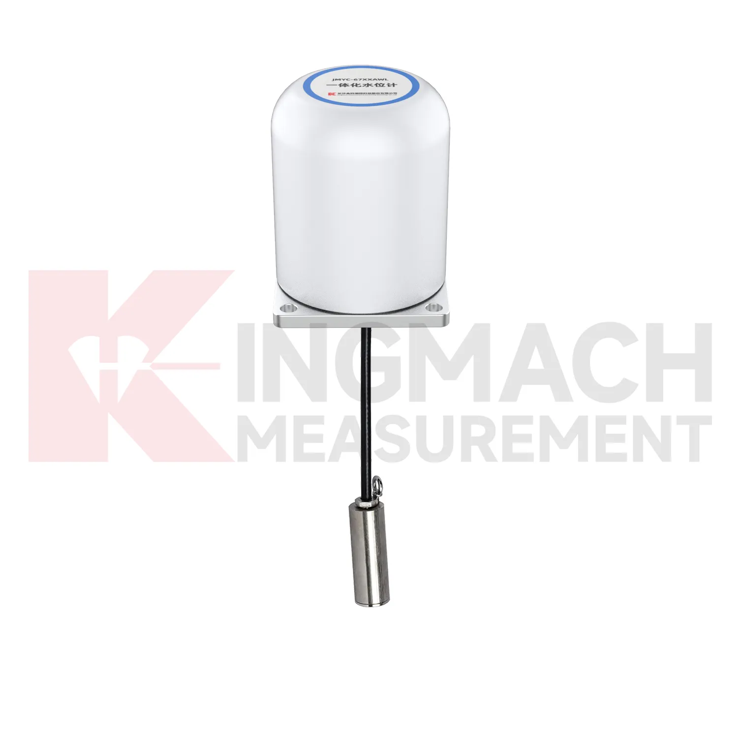
For load cell wiring diagram connected to automated acquisition, maintenance is partly physical and partly digital. At installation, confirm sensor model, range, channel number, unit, calibration coefficient, zero value, and temperature channel before the point is accepted. Smart load cells may store calibration information and up to 800 measurement records, while digital output and anti-interference transmission help long cable runs. During operation, review missing data, repeated identical values, sudden jumps, and temperature related drift. Physical checks should cover waterproof connectors, cable strain relief, grounding, lightning protection, junction boxes, and power supply stability. After any software or logger change, verify that kN or MPa units remain correct and that historical trends did not shift because of scaling errors. Where alarms are used, test the alarm path without applying dangerous loads. A good maintenance routine protects the instrument and the database at the same time, because either one can damage confidence in the monitoring record.
Kingmach load cell wiring diagram
load cell wiring diagram is useful where the risk is not dramatic movement but slow, uneven load transfer. A bridge cable may relax in small steps, a support jack may settle after locking, a foundation pit strut may gain force overnight, and a dam anchor may respond to water level changes. Kingmach force monitoring products are designed for these long observation periods, with smart chips, temperature correction, waterproof structures, and compatible readouts or acquisition units across several models. The working value comes from repeatable measurement under real site conditions. That includes dust, water, vibration, long cable runs, tight installation space, and crews working around the instrument. A good record helps teams separate normal load fluctuation from a developing problem. It also reduces arguments during handover, because the reading is tied to a named point, a calibrated model, a timestamp, and the same measurement method used throughout the project. The result is a record that can survive handover between contractors and owners.
FAQ
Q: What does load cell wiring diagram do in a foundation pit or tunnel? A: It measures axial force in steel supports, anchor load, or pressure change as excavation and support stages progress. Q: Which Kingmach model fits steel support axial force? A: The JMZX-38XXHAT axial force meter is listed from 200 kN to 3000 kN, with 0.1 kN or 1 kN sensitivity and 0.5%FS accuracy. Q: Is it suitable for wet underground sites? A: The axial force meter lists a 1 MPa waterproof rating, but connector sealing and cable routing still need inspection. Q: Why is direct kN display useful? A: It reduces confusion because teams can read axial force directly instead of converting vibrating wire frequency on site. Q: What should trigger extra checks? A: Excavation step changes, rainfall, dewatering, support adjustment, sudden force jumps, or unstable channels.
Reviews
Christopher Martinez
Very satisfied with the readouts & data loggers. User-friendly interface and supports multiple sensor inputs.
Joshua Clark
We ordered a full monitoring solution including sensors and data loggers. Everything works seamlessly together. Great supplier!
Latest Inquiries
To protect the privacy of our buyers, only public service email domains like Gmail, Yahoo, and MSN will be displayed. Additionally, only a limited portion of the inquiry content will be shown.
Harper***@gmail.comIndia
Dear Sir, we are planning to procure a complete monitoring system including strain gauges, tiltmeter...
Sophia***@gmail.comUnited Kingdom
Good day, we need environmental monitoring sensors including temperature, humidity, and wind sensors...